
|
|
Alison Stewart |
|
Modelling and Simulation Based Design of GUI BehaviourIntroduction The purpose of the project was to investigate modelling and simulating graphical user interface (GUI) behaviour. The end goal of the project was to find the best modelling formalism to model and then simulate the GUI behaviour of the icon editor for AToM3, a tool for multi-paradigm modelling, developed by the Modelling, Simulation and Design Lab. The two candidate formalisms, statecharts and DEVS, were chosen by Professor Vangheluwe. An MP3 player was modelled and simulated using each of the candidate formalisms for exploration purposes to aid the decision of the formalism to use in modelling the icon editor. Statecharts Formalism Harel's statechart modelling formalism provides a visual representation of state that is intuitive, and also quite familiar to programmers who have experience with state automata from theory courses. The statechart formalism is based on state automata with the addition of hierarchy and concurrency. The hierarchy of statecharts provides a surprising amount of expressiveness in comparison to state automata. The transitions of a parent state take precedence over those of its children, so that parent states serve to unclutter the statechart by avoiding the need for each child state to show a transition originating from a parent state. The groupings provided by parent states also allow the viewer of the statechart to consider the system at several different levels. Rather than go through each state to understand the statechart as is necessary with state automata, the viewer can consider a high level view without looking inside parent states to get an overview before considering any children states. Within a parent state one of the children states must be specified as the default so that unless a transition points to another specific child state entering the parent state also enters the default child state. Parent states may also contain a history state, which isn't actually a state itself. Instead a transition pointing to the history state signifies that the new state is the last entered child of the parent state. Concurrency within statecharts also cuts down on the necessary number of states needed to express a system. By showing that a state within the group of states A is being chosen concurrently to a state within group of states B, the need to have states for every combination between the groups A and B is eliminated. Explicitly showing the concurrency also makes statecharts more understandable than deducing that the concurrency exists from seeing the list of necessary combination states in the state automata. The transitions from state are triggered by an event, and a triggered transition can also broadcast another event. An event seen by one part of the statechart is seen by the entire statechart. For the statechart formalism to accurately describe an application it must be expanded. To give the statechart memory without an infinite number of states, variables must be introduced, and another necessary feature is that functions must be called. The most logical way to consider these extensions is by extending the output or broadcast event of a transition and widening the concept of the event to include actions. These actions can also take place when entering or exiting a state which cuts down on repetition within the output of transitions. Applied Statecharts 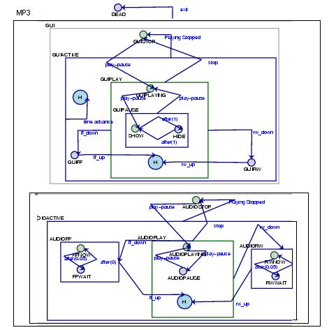
When using statecharts to model the MP3 player I found that the visual representation of statecharts gave an excellent way to consider the application design. The event-action paradigm created by the structure of the transitions in the statechart formalism was ideal for dealing with user interaction. At first my statechart design of the MP3 player had states and transitions that dealt with both the necessary audio operations and GUI operations. At the suggestion of Professor Vangheluwe I separated the audio and the GUI to consider them instead as each having states running concurrently to each other. The concurrency shown for the MP3 player doesn't actually simplify the statechart in the manner described when introducing concurrency above. Rather than the statechart needing less states to describe the system by virtue of combinations between the concurrent parts this lead to more states due to duplication between states needed for both the GUI and the audio portions of the application. However, when modelling the GUI and audio portions each one had areas where children states were required that were not necessary in the other part. Splitting the states increased the size of the statechart, and increased the number of transitions waiting for the same event from the user, but made the extra children states easier to understand by giving them an immediate visual context: as necessary for either the GUI or for the audio portion. As well as initially editing the statechart for logical errors, designing the statechart for the MP3 player gave the importance of a multi-step design process in which details are modified after looking at practical issues. Originally for the audio portion of the MP3 player I had designed the statechart so that when the user pressed the fast forward button (and equivalently for the rewind button) from playing or paused a fast forward state would be entered, and then after a time elapse spent fast forwarding would return to the previous state. This was a naive view of the driver functions for the MP3 player in combination with user interaction. A function was available to fast forward the track by a given amount of time, which would have followed the model if the value of time of time to be skipped was passed using a variable. If the way the driver worked meant that a larger period to skip would take longer then a function using this variable would also be needed to alter the time elapse before going back to the previous state, which is also feasible. The problem is the entering of a specific value to be skipped during the track. The standard CD player or MP3 player interface doesn�t work this way. Instead the user expects to hold down the fast forward button for an amount of time less than, but proportional to, the amount of time that should be skipped. This system is probably entrenched in users� minds from the days of cassette players. Considering an MP3 player which skips portions of the track while the fast forward button is held down meant changing the model from noticing one GUI event to enter the fast forwarding state, and then a transition triggered by a time elapse to return to the previous state, to the same event trigging the transition to the state, but noticing another GUI event, the release of the fast forward button to return to the previous state. Within the fast forwarding state it is now necessary to insert two child states. From the default a transition fired immediately has the output action of calling the fast forward function with a chosen base increment of time. After the time taken to make this skip, a transition triggered by the time advance will enter the default state of the parent fast forward state again. This is one example where the addition of children states was necessary in the state for one concurrent portion (here the audio portion) while unnecessary for the parallel state in the other side of the concurrency (the GUI). The statechart model of the MP3 player was simulated using Thomas Feng's Statechart Virtual Machine (SVM). SVM can run with a GUI showing the states with hierarchy, the current state and a list of possible transitions from that state. The user can select transitions and see the change of state. SVM also allows the user to raise events for the event handler of SVM from actual code and run the application using SVM with functions called as actions in the output event of transitions, or on entering or exiting a state as discussed in the extension of statecharts. The simulation of the statechart gave a working and convenient to use MP3 player. DEVS Zeigler's DEVS (Discrete Event Systems) also extends State Automata and allows modelling of systems in which within any specific time frame a finite number of events occur. An atomic DEVS describes scheduled events which change the state of the system. An atomic DEVS is a module which can send messages if warranted by its state (as the change in states is scheduled this also means that sending messages is scheduled), and can also receive messages that are specifically passed by another connected atomic DEVS and react to the messages, which function as interrupts. Looking at the system from a level of connected atomic DEVS we have coupled DEVS. Two atomic DEVS which are coupled function completely independently until a message is passed between them. This behaviour is similar to concurrent parts in statecharts, although there both parts can see any event seen by the other part whereas in a pair of connected atomic DEVS one may receive a message from another atomic DEVS it is connected to which is not sent to the other one. This modularity is on of the main benefits of using DEVS. DEVS are also more powerful than statecharts because they are less restrictive. While this gives DEVS the ability to model more phenomena, it also means that creating a visual representation of DEVS is more difficult. Applied DEVS For the MP3 player application used to investigate the formalism, the perfect modularity of DEVS wasn't entirely necessary. The messages came through the Tk GUI which I didn't need to design, and then generally needed to be seen by the rest of the system. To construct Atomic DEVS on the basis of what parts need to see which messages would have an atomic DEVS containing the Tk GUI which would send messages about user interaction to the equivalent of the concurrent GUI part of the statechart mentioned above, here an atomic DEVS, as well as to the concurrent audio part of the statechart, here another atomic DEVS. These atomic DEVS would send messages to the python code for controlling the GUI and audio drivers respectively, which pass messages to the Tk GUI the drivers. There is also an instance of communication between the atomic DEVS for the GUI design and the python code that communicates with the drivers because it keeps track of the current place in the track which is needed for the GUI time display. Most of these atomic DEVS are outside the area of interest because the parts have already been designed. Within the two atomic DEVS of interest both need to receive the same messages from the Tk GUI and do not communicate with each other. The system could be separated into more atomic DEVS, roughly equivalent to the number of states in the statechart version (although atomic DEVS for children connected by transitions triggered by time advances would be unnecessary as discussed later). However, this involves sending messages to all of these different atomic DEVS (since the atomic DEVS are interested in most of the possible messages) when the message isn�t needed by the majority of these DEVS, only one, decided by the overall state. This solution was implemented using Spencer Borland's RT_DEVS (real time DEVS) translation from statecharts (and the model used above) to DEVS. For the MP3 player, which does receive a continual time advancement message, when the messages passed were printed out after four seconds of play it would take that long again to react to the user pressing the stop button! Even without a printout of the messages being passed, a backlog of messages would build up so that an even longer delay would occur before the appropriate action would occur in response to a user request a minute into an MP3 file. With these response times the application simply wasn�t practical. Another issue in modelling the MP3 player using DEVS is the lack of scheduling necessary within it, so that the MP3 player doesn�t take advantage of a major quality of DEVS. User input is very important to the MP3 player application so there are actions taken reacting to external messages, and otherwise only scheduled events where there were transitions triggered by time advances in the statechart (when in pause for the GUI and fast forward and rewind for the audio). Observer Pattern 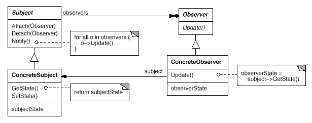 Image from Design Patterns
Investigating the MP3 player gave me experience in modelling an application with actions resulting mainly from user interaction, which is also the case for an icon editor. However, when Professor Vangheluwe was describing possible extensions to AToM3, one was the ability for several users in different places to observe the same AToM3 canvas, which created new needs. The behaviour needed to implement this extension is described in the Observer pattern, also known as Subject-Observer, Dependents, and Publish-Subscribe. The diagram expresses that the Subject can attach an Observer (Attach(Observer)). The Subject contains the current state, which can be set using the SetState() function. Once a change has been made the Subject calls the Notify() function and notifies all attached Observers, at which point an Observer can call its Update() function so that the GetState() function is called in the Subject and the subjectState returned. An Observer can also be detached from the Subject (Detach(Observer)), after which it will no longer receive any notifications (or updates) from the Subject. The body of these functions can be written so that Notify() informs the Observers the type of information changed in the Subject so that an unnecessary Update() is not called by the Observer. The amount of information returned to the Update() function may also be reduced by specifying the portion of the state that is of interest to the specific Observer. Many programmers will be familiar with the Observer pattern through the Model-Control-View (MVC) paradigm used as a framework for the user interfaces in Smalltalk. Choosing a Modelling Formalism for the Icon Editor The experience of modelling the MP3 player led me to prefer the statechart formalism for an application which changes state mainly due to user interaction and its simple representation of hierarchy. The addition of the need to implement an Observer pattern complicated matters though. The idea of a Subject and Observers gives distinct modules with actions necessary when communication takes place between them. These attributes clearly fit with the DEVS formalism. The solution to this was to create different statecharts for components in the Observer pattern, and then treat them as atomic DEVS coupled together in terms of passing messages between them. This decision was made much easier by the fact that Thomas Feng had just begun work on ports for SVM. The ports allow messages to be sent specifically from one statechart to another and be seen as an event in the second statechart which may trigger a transition. Instead of a separate set of instructions for incoming messages into an atomic DEVS, a message from a specific input port is an event and is dealt with using the same rules as the other events, although in this case the event can have different contents each time it is raised. Separate statecharts now follow the modularity of DEVS. 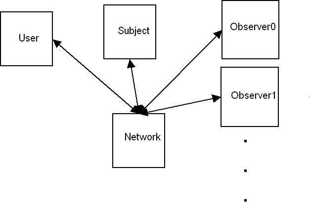
Modelling the Icon Editor Instance of the Observer Pattern As stated above, the Observer pattern level of the model can be viewed as coupled DEVS. The SetState() call has stayed within the domain of the Subject, but the impetus to perform this action comes from another module called the User (similar to the MVC version of the Observer pattern). This model assumes that there is just one instance of the User, but the design could be altered so that there could be several Users with communication to the Subject buffered by a manager implementing a queue, or choosing between information sent based on a level of priority given to the different Users. Since this model assumes that only one User exists (perhaps by using the Singleton pattern when starting the application), if several Users were allowed the model could also have an attach and detach process for the Users so that permissions could be established and used in the manager of the information being sent to the Subject for use in a SetState() function call. This would create the need for messages from the Subject to the Users through the network. An arrow in this model from the Network module to the User module exists solely for the possibility of receiving errors from a real network while implementing several Users would involve actual communication to the Users as well as the extra module to manage their outgoing messages. The Network 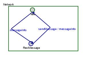
The model of the entire system shows the Network, at the equivalent of the coupled DEVS level, as the hub of the message activity. When actually implementing the icon editor, this �module� already exists and can be removed. Since the network was not a primary concern I modelled it very simply. When the network receives a message it sends that message on. In terms of statecharts this behaviour could actually be modelled using one state and one transition. In that case an incoming message would trigger the single transition, and as the output event the network would call the necessary function to forward the message sending out the information. After all, unlike the Observer which will be notified, and then some decision and subsequent action of the user is needed before responding to that event, the network always wants to react to the incoming information. My somewhat false statechart representation was done to show that there can be a time gap between receiving and sending a message, which is not as clear with the one state and one transition version. The second transition is actually triggered by a time elapse which can be set to see what happens in the model when messages are lost (here because the network is busy with another message). A more robust network might consist of queuing all incoming messages and sending messages from the front of the queue when not busy receiving messages. The User 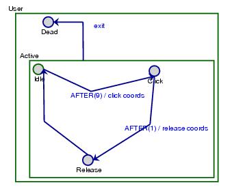
To model the interaction of a user with the other modules the User statechart just produces user output. Here information sent is considered to be just the information that a mouse button has been clicked, and its coordinates, and that a mouse button has been released, and its coordinates. Unless the user wishes to perform operations without being able to see the canvas he will have also registered an Observer. This User-Observer package could work more like an independent icon editor and translate the user mouse interaction into higher level ideas to transmit to the Subject (such as sending the information that the user has selected a different mode rather than just sending the mouse coordinates clicked). However, the more actions performed by the User, the more control is given up by the Subject. In this creation of a pretend user transitions are scheduled and this module could have been modelled using an atomic DEVS. Once an actual user is in place though, the sending of information would no longer be scheduled. The Observer 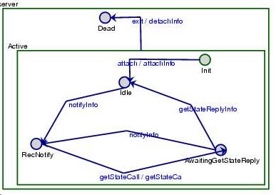
The Observer statechart shows the Observer side of the design pattern. When the Observer is sending a message I showed the output event as the information from an action taken rather than the function call itself. This is a more realistic view of the network, and because the event triggering the transition is actually the user causing the function call to be made. The transitions which have output events are shown having the calls being the events, although without having an actual user to cause these functions to be called the real trigger for these transitions is a time delay. This model of the Observer assumes that when the Subject sends the update information it sends the entire canvas. If the Observer is waiting for an update and receives another notification interrupting its GetState() call (provided the Observer is interested in the area the change took place) it returns to its previous state and then requests another update. During this time, according to this model, it may miss the first update. If the Subject is only giving the newest information the previous change will be lost to the Observer and it will not be consistent with the Subject. However, if the Subject is very slow sending updates this model of the Observer will be waiting for the second update, receive the first, and assume that it is finished with update information and actually not be synchronised with the Subject until it next receives a notification of interest. I was hesitant to always react to update information during any state in the Observer because then the Server might be sending uninteresting information (although it shouldn�t). This may be paranoid since the Subject is given control of the state of the application perhaps it should also be trusted to properly send out the state information. The Observer expecting to receive information also does not guarantee it is getting the correct information, although it is more likely what the Observer wants if the Observer is expecting to receive information than not expecting to receive information. The most paranoid view would be to insist that updates be sent with a header that corresponds to an update, and for the Observer to keep a list of desired updates chosen from the notifications. The least paranoid view would be to simply accept any update the Subject chooses to send to the Observer, trusting that it is properly answering the Observer and accept this information and return to a history state without worrying about separate GetState() calls giving return values (separate the call from the return). The Subject 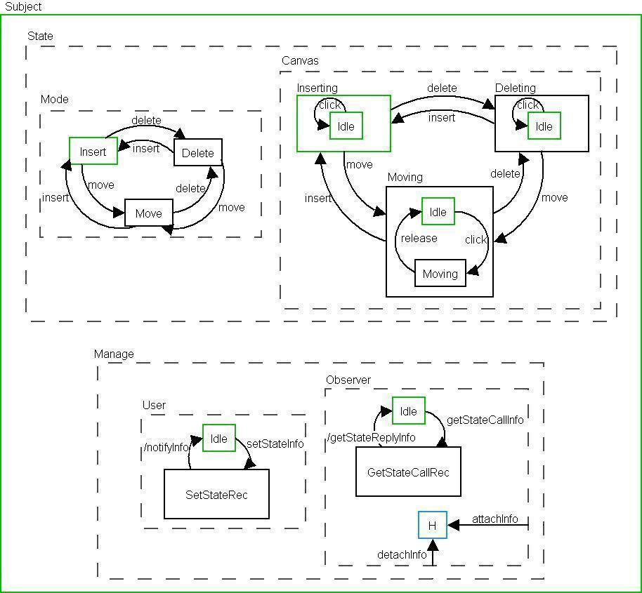
The Subject is split into two main parts that run concurrently. One of these parts, Manager, models the necessary communication of the Subject with the other parts of the Observer pattern. The other part, State, models the current state of the application. In the diagram included there are concurrent states within concurrent states which is not allowed in the entity relationship diagram of statecharts in AToM3. There is also a transition from a concurrent state to a history state within it which is also not allowed by AToM3. I have not found a reason within statecharts to disallow these things, so to make the diagram clearer I have not inserted dummy default states in the hierarchical level inside these concurrent states. The State state in the Subject is quite simple. The Subject keeps track of what mode the editor is currently in, and what it is doing. The actual data for the canvas is stored in state variables. It is written and changed during transition output event actions within the Canvas state in one of its Inserting, Deleting, or Moving children states. The Mode state keeps track of whether the icon editor is in Insert, Delete, or Move mode, which in the GUI of the icon editor are shown with radio buttons to alert the user to the current mode. This state information is already included in the Canvas state because events must be interpreted differently within the Canvas state depending on the current mode (ie. a mouse click in the insert mode inserts a rectangle at that location, which a mouse click in the delete mode removes the nearest rectangle). The Mode state could be scrapped and its output events transferred to the appropriate transitions in the Canvas state, but I found that the statechart was easier to read when each segment of the GUI was represented separately. The Canvas state needs the current mode to perform the appropriate action on the canvas of the GUI, while the Mode state needs the current mode to alert the user of it visually on the GUI. The idea that the Canvas state uses the mode during an action makes giving it the active form of the mode appealing as it also lessens confusion when discussing the Mode and Canvas state. Unfortunately I can�t claim the credit for it though as I took the active naming from Professor Vangheluwe when comparing my statechart model of the icon editor to his to avoid the repetition I had. The Manage part of the statechart shows the necessary states and transitions to deal with this side of the Observer pattern. The User state, which is concurrent to the Observer state, deals with the event of information coming in from the User with the output event action of a SetState() function call. Although it takes place within the User state, the other transition actually deals with the Observers to the Subject, as the Subject must notify all Observers of its change of state. The transition outputting the notifyInfo, and triggered by a time elapse could be combined with the transition triggered by the setStateInfo. The separation was just made to consider the dynamics of the parts of the network working together and what would happen with different time delays, which were discussed above when considering the Observer. Simulating the User state was a problem in SVM. SVM allows calls to be made to code in conditions for transitions and their output events, but does not allow looping or branching within the transitions themselves. In this case the transition should be triggered and then in its output event a message sent to every attached Observer. To accomplish this the output event must send an identical message to each Observer, but with the destination (which will be used by the server) changed. Using a function call, which can iterated over the list of attached Observers, cannot dynamically change the already running SVM and so cannot solve the problem. For the SVM simulation I used a duct taped method which hardcodes sending the message to both Observers which are on the Network which is clearly wrong � it should have checked whether or not these Observers are actually attached. A slightly more correct method would be to hardcode in a transition to all Observers on the Network (although more could be added so that this could miss Observers) and then use a function call which iterates through the list and returns true if the Observer is currently attached. This method increases the amount of code, and since both methods are wrong I chose the shorter one to code so that it would be clearer to the reader. One other solution would have been to have a function call iterated through the attached Observers and return a string with the address of each in port. This would involve changing the structure of messages within the Network though. The Observer state deals with Observer responses to notifications. The first transition is triggered by information sent by the getState() function in the Observer, and the second transition sends back the return value to that function. Like in the User state these transitions could be combined, and are only split to explore timing issues so that the second transition is triggered by a time elapse. The possible time differences this allows were discussed with the Observer. Future Work and Conclusions Obvious future work here is raising events in the icon editor code run the application using the model in SVM. The model could then be expanded from the simple icon editor to the comprehensive icon editor created for AToM3 by Francois Plamondon. Another possible (but quite daunting) project would be extending SVM to include branching and loops so that output events of transitions could change depending on the extended state. I use the term extended because the information causing the changes would be stored in state variables; if the total state were expressed using traditional statecharts the transition would be for a specific state and this would be unnecessary. I found that modelling and simulating applications lead to a more careful consideration of their organisation. Running the applications using modelling tools sometimes provides a sturdy application, but for now should generally be considered a design phase rather than a finished product due to the limitations created by the lack of branching and loops in SVM and the sometimes excessive message passing of DEVS causing the application to run slowly. An example of a sturdy program run using modelling tools is the MP3 run using SVM. The lack of branching and loops in SVM posed problems for the icon editor when using the Observer pattern with it, and while using RT_DEVS would have eliminated such a problem from the icon editor its problems created with large amounts of message were a problem for the RT_DEVS MP3 player. In general I found modelling in statecharts preferable to modelling using DEVS. The restrictions of statecharts actually make planning easier because there are well defined boundaries on actions, so that they can be easily visualised, and so that the simplest and most elegant solution can be discovered. In general I would model using statecharts and then consider whether everything necessary could be accomplished. Once reaching a point where statecharts are unable to model behaviour the power of DEVS is useful, but even reaching this point through statecharts is beneficial because the modeller will be thinking of the minimum change to statecharts that would be necessary and hopefully keep a simple design once delving into the power of DEVS. Appendix Statechart MP3 Player SVM .des File DEVS MP3 Player AToM3 Diagram Python File RT_DEVS File SC2DEVS_MODEL.py (structure) Icon Editor Network SVM .des File Icon Editor Network AToM3 Diagram Python File Icon Editor User SVM .des File Icon Editor User AToM3 Diagram Python File Icon Editor Observer SVM .des File (Example Observer0) Icon Editor Observer SVM .des File (Example Observer1) Icon Editor Observer AToM3 Diagram File Icon Editor Subject SVM .des File Icon Editor Subject SVM Python Helper File Icon Editor Subject AToM3 Diagram Python File | |||||||||||
