Evolution of modelling languages
and the co-evolution of modelling artefacts
I realize that some pictures are still drawn by hand and photographed. I'm not really planning on fixing this.
Problem description
In model-driven engineering, not only instance models, but also entire modelling languages are subject to evolution. This is in particular true for domain-specific languages (DSLs), whose language constructs are tightly coupled to an application domain. Up to this day, modelling languages are evolved manually, with tedious and error-prone migration of artefacts such as instance models as a result.
In multi-paradigm modelling (MPM) a system is composed of a heterogeneous set of models, written in different languages. Relations exist between the models, and are implemented as model transformations.
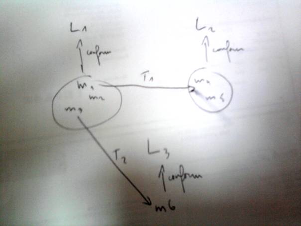
Figure 1: An MPM system
If e.g., language L1 in this system evolves, the system is not consistent anymore (meaning that the given relations of conformance do not hold anymore). The most obvious example is that instance models m1, m2, m3 may not be conform to L1 anymore. They need to be co-evolved with the L1 change. Also, transformations T1 and T2 will have to co-evolve.
Research goal
The research goal is twofold:
· Provide automation for co-evolution of modelling artefacts;
· Provide a complete ontology for this automation.
A remark has to be made by the first goal: full automation will be impossible. Co-evolution must be as automated as possible, but never at the cost of correctness.
The second goal means that we do not wish to limit ourselves to meta-model evolution and instance model co-evolution. Other topics are e.g., transformation model co-evolution, evolution of language semantics (see also open problems).
Overview
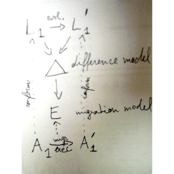
Figure 2: Overview of co-evolution
This figure presents an overview of the co-evolution process. A language L1 evolves to L1'. The difference is modelled in a difference model Δ. This is a model that formally represents the difference between L1 and L1'. From Δ, a migration model E can be created. E is a transformation model that transforms artefacts like A1 to A1', so that A1' conforms to the evolved language L1', as intended.
When looking at this figure, automation can be one of the following:
· Full automation (A0). This highest form of automation can be implemented in the framework itself. No manual intervention is required whatsoever. This is achieved when Δ can be created automatically and E can be automatically created from Δ;
· Evolution-specific automation (A1). This form of automation is achieved when the creation of E requires some manual intervention but E can be executed without manual intervention. Manual intervention must be done once for a language evolution;
· No automation (A2). When the execution of E requires manual intervention. The number of manual interventions is proportional to the number of artefacts that have to be co-evolved.
Further in this document, we use these classification on parts of the co-evolution. So some parts can be A0, while other parts are A2. Of course, in total this would result in a co-evolution that requires manual intervention for each artefact that must be migrated. The goal is then to limit the amount of manual work that must be done per artefact, by limiting the parts that are A2.
Setting
In the domain of MDE, we consider a system as a collection of models. A model m can be represented in its system by a number of relations:
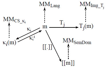
Figure 3: a model and its relationships in MDE
In this figure, m is conform to its meta-model MMLang. There is a semantic mapping [[.]] to a semantic domain SemDom. There is also one or more concrete syntax representations CS_Кi, with a rendering function Кi and a parsing function Кi-1. Furthermore, other transformations (from and) to other languages such as Img_Tj can be defined. This diagram is composed of models, transformations and conformance relations. When developing the system, each of these artefacts can evolve, possibly causing other artefacts to co-evolve. The above system can be considered the application of several instances of the following diagram:
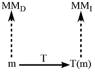
Figure 4: The basic evolution architecture
This diagram consists of a domain language D and an image language I, with a transformation T in between. Note that the current state of the art of modelling language evolution only considers the conformance relationship between instances (m) and meta-models (MMD) as the subject of evolution and co-evolution. First, it is our goal to study evolution of every of the five artefacts shown in the diagram above, and co-evolution of any other artefacts in the diagram if necessary. Second, we study how different relationships in Figure 3 should be treated.
As a running example, we use a RailRoad DSL as domain language and Petri nets as image language. The meta-model of RailRoad is as follows:
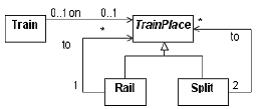
Figure 5: RailRoad meta-model
A Train can be on either a Rail or a Split. Rails and Splits are connected to form a railroad system. An example of such a system is the following:
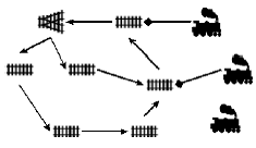
Figure 6: A RailRoad model
Note that one Train is not on a TrainPlace (possibly meaning that it is in the depot).
The Petri net formalism is well-known:
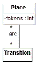
Figure 7: Petri net meta-model
The simplified transformation between RailRoad and Petri net is shown with an example:

Figure 8: RailRoad to Petri net transformation
Differences between models
In order to provide automation, the difference between the two versions of the artefacts under evolution (e.g., meta-models) must be obtained and modelled precisely.
There are two ways to obtain the difference between two models. The first is to record them, and the second is to use an algorithm to calculate them.
There are two ways to represent a difference model. The first is the operational representation, which lists the operations that are performed on the model. The second is the structural representation, in the model (or its document object model (DOM) representation) is coloured or a designated difference model is created which can be used by modelling tools as yet another model. Consider this simple class diagram example where the male and female classes are added:
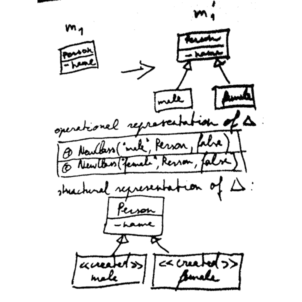
Figure 9: Simple example of difference representations
The operational representation in the figure is based on Herrmannsdoerfer et al. [2], and the structural representation is based on Cicchetti et al. [3]. Note that there is a notion of order in the operational representation.
The operations that are performed on models can be thought of as CRUD (create, read, update, delete) operations on every meta-class (note that read can be omitted). In simple class diagrams, this would result in create class, update class, delete class, create property, update property, delete property (where property is an attribute or association). Interestingly, all possible changes can be deduced from the meta-model [3].
For the remainder of this document, we assume that class diagrams is the meta-language (i.e., the language in which we write our meta-models). In order to maximize automation, a more elaborated set of possible changes will be used, as explained in the next section.
In our example, consider the evolution of the RailRoad language. The meta-model of Figure 5 evolves to the following:
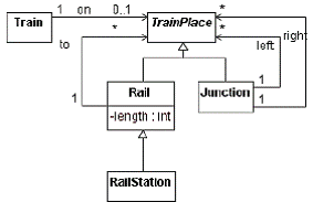
Figure 10: Evolved RailRoad meta-model
Trains must be on a TrainPlace, Split is renamed to Junction, a RailStation is introduced, a Rail can have a length and a notion of left and right is added to the Junction. The operational difference is represented as follows:
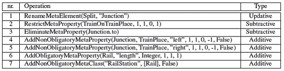
Figure 11: Operational difference of the RailRoad evolution
Note that 3, 4, and 5 can be bundled to the change "add a notion of left and right to the Junction".
A migration model
In this section it is explained how a migration model can be created, as automated as possible.
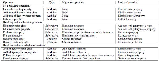
In the previous section it was shown that changes can be broken down into basic change operations. In the table below, a set of change operations is given, based on [4].
1) For these operations, the classification is given, denoting the need for co-evolution*:
· Non-breaking operations: operations that do not require any co-evolution action, as they do not break the conformance relationship;
· Breaking and resolvable operations: these operations break the conformance relationship and require instance model co-evolution. However, this co-evolution has to be created once and can be reused for every instance model (A1 automation);
· Breaking and unresolvable operations: no general co-evolution that is applicable for every instance model can be found and the instance models will have to be co-evolved manually (A2 automation).
* Note that this classification is valid for instance model co-evolution, not transformation model co-evolution. For transformation models, the classification of operations can be stricter (e.g., when a non-obligatory meta-class is added, it is generally desirable that outgoing transformations can map this new construct onto a construct of the image language, so that the transformation implements a total function).
2) When thinking of CRUD, an operation can have one of three following types:
· Additive (A): the number of possible instance models that are conform to the language has increased;
· Updative (U): the number of possible instance models that are conform to the language is exactly the same;
· Subtractive (S) : the number of possible instance models that are conform to the language has decreased;
3) A default migration strategy can be devised. Of course, no migration is necessary for non-breaking operations. Note that an operation can have more than one sensible migration operation.
4) For every operation there is an inverse operation, which can also be found in the list. This will be important further in this document.
Co-evolution of instance models
A migration model will consist of a chain of migration operations, called the migration transformation. Input for this chain will be an artefact conform to the old version of the language, and output for this chain will be this artefact conform to the new version of the language.
From the difference model, a migration transformation can be generated consisting of the default migration operations. The migration transformation is highly modular. In practice, it consists of a transformation for each migration operation. The migration operations can be reordered (with some restrictions, see open problems), replaced with user-defined operations, and combined into user-defined operations. The edited migration operations are A1 automated or worse.
For the evolution of the RailRoad language, the following migration transformation can be used:
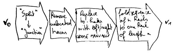
Figure 12: The migration transformation for the RailRoad evolution
Four operations are created:
1. Split elements are replaced with Junction elements (see 1 in Figure 11). This is the generated default migration operation (A0 automation);
2. Trains that are not attached to a TrainPlace are simply removed (see 2 in Figure 11). This is the generated default migration operation (A0 automation);
3. to-links are replaced with left- and right-links (combination of 3,4,5 in Figure 11). The choice must be made for each model (A2 automation);
4. A sequence of n Rails (with n between 1 and infinite) is folded into one Rail element with its length attribute set to n (see 6 in Figure 11). This migration operation replaces the default one, but it can be executed automatically (A1 automation).
Note that change 7 is not included. In fact it is included, and its default migration operation (do nothing, which can be considered the identity function) is used.
This approach works fine for instance models, but not for transformation models. If a transformation model would be simply transformed by a migration transformation, a lot of (superfluous, as we will see) manual work must be done afterwards.
Co-evolution of transformation models
In order to co-evolve transformation models, we go back to the basic architecture of Figure 4. Suppose that the meta-model MMI evolves. We call this image evolution:
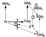
Figure 13: Image evolution
As shown in the overview of Figure 2, a difference model is created in a first step, next, a migration transformation is created to co-evolve instance models T(m). In a third step, the transformation model T has to be co-evolved. As the diagram suggests, T' can be obtained by first applying T, followed by E. So T'=E○T. This means that the new transformation consists of applying the old one, which results in a version 0 MMI artefact, followed by the application of the migration transformation on that artefact, resulting in a version 1 MMI artefact.
When MMD evolves instead of MMI, a similar commuting diagram can be seen, but this time T'=T○E-1. So version 1 instance models are transformed back to version 0, and then the old transformation can be applied:
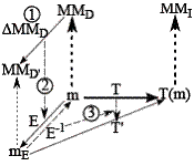
Figure 14: Domain evolution
Note that these equations are only fully applicable when both versions of the evolved language are equivalent (i.e., in the case of updative changes). Otherwise, there is a risk of losing information when transforming back to the old version. Of course this is quite undesirable, as the evolution was designed specifically to implement this new information. However, the principles can still be used for co-evolving transformations.
Consider the figure below. It represents image evolution, just like Figure 13, but at a more detailed level:
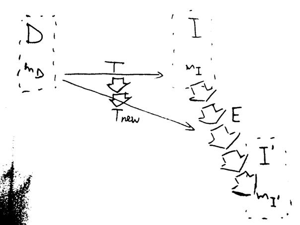
![]()
Figure 15: Image evolution in practice
Again, I is evolved to I', and its instance models are co-evolved using E. Note that E is divided into modular migration operations. Instead of using T'=E○T, T is migrated to Tnew, but only for the changes that involve new information. As a result, T' is now composed of first executing Tnew, which results in an artefact somewhere in between I and I', and next transforming this artefact using the remainder of E, so that it conforms to I'. This way, the manual co-evolution of T is reduced to a minimum.
Domain evolution can be obtained similarly:
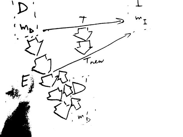
Figure 16: Domain evolution in practice
Note that the inverse migration operations are required for some, but not all, of the migration operations of E.
Below, some examples illustrate the presented approach. First, consider once again the transformation from RailRoad to Petri net shown in Figure 8. After constructing the migration transformation E as in Figure 12, the transformation can be co-evolved as follows:
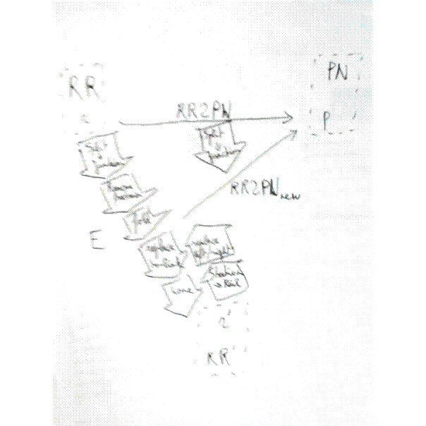
Figure 17: Domain evolution in practice for a RailRoad to Petri net transformation
A remark has to be made on the RR2PN transformation. It is introduced to analyse RailRoad models for deadlock detection.
Note that E is reordered in the figure above: the replace to-link operation has swapped with the fold operation. Also, the identity transformation for the "add RailStation class" change (which is a non-breaking change) is included, as it inverse is breaking. In order to co-evolve the transformation model, all occurrences of Split are replaced with Junction in the transformation model. Executing the co-evolved transformation is as follows: first, all RailStations in r' are replaced by Rails. Next, the left- and right-links are replaced by to-links. Then, the transformation is executed, by ignoring the length of the Rails. In short:
1. First, replace Splits with Junctions in the transformation model;
When executing the co-evolved transformation on an instance model:
1. Replace RailStations with Rails in instance model;
2. Replace left- and right-links with to-links;
3. Execute co-evolved transformation.
Note that the "remove unallocated train" operation and the "fold" operation are not taken into account when co-evolving the transformation. This is correct, since unallocated trains or folding sequences of Rails does not influence the outcome of the deadlock analysis.
Also note that instead of applying the "Split to Junction" operation on the transformation, its inverse could have been applied on the instance model. This way, the transformation did not need to be touched altogether.
A second example involves a transformation that transforms RailRoad models to Java code:
![]()
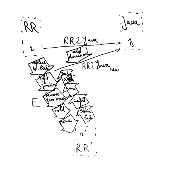
Figure 18: Domain evolution in practice for a RailRoad to Java transformation
Note that the E is again reordered. This time, the transformation needs to be co-evolved by manually adding the notion of direction to RR2Java. This can be done by changing the rule that transforms a Split. When executing the co-evolved transformation, r' is transformed back to RR except for the left- and right-links. In other words, the newly introduced information about direction is preserved. Finally, the transformation is executed. In short:
1. First, add notion of direction for Java code the transformation model;
When executing the co-evolved transformation on an instance model:
1. Replace RailStations with Rails in instance model;
2. Unfold rails: Rails with length n become n Rails with length 1;
3. Replace Junctions with Splits;
4. Execute co-evolved transformation.
A last example involves a transformation that implements a simulation step for the RailRoad language. It is an endogenous transformation. The transformation simply navigates a Train over the RailRoad model.
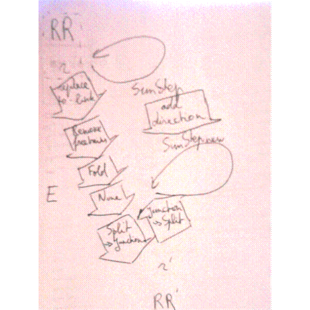
Figure 19: Domain evolution in practice for a RailRoad simulation step transformation
Again, E is reordered, and again, the notion of direction is manually added to the transformation model. When executing the co-evolved transformation, Junctions are first renamed to Splits. Then the adapted transformation is applied. Finally, because this is also an example of image evolution, Splits are again renamed to Junctions. In short:
1. First, add notion of direction for Java code the transformation model;
When executing the co-evolved transformation on an instance model:
1. Replace Junctions with Splits;
2. Execute co-evolved transformation;
3. Replace Splits with Junctions;
Note that the Junction/Split replacement could also have been applied to the transformation model itself, avoiding step 1 and step 3 for each instance model. The other migration operations (unlocated Trains, fold, RailStation) are not taken into account for this transformation, as they do not affect the behaviour of the simulation step transformation, which simply involves Trains moving over TrainPlaces. Note that, while before a sequence of n Rails took n simulation steps to traverse. In the new version, a Rail of length 1 only takes one simulation step to traverse. Another evolution could incorporate a notion of position on a Rail.
Advantages of co-evolving transformation models using the presented approach are:
· Adaptation of transformation model is minimal (at most 1 adaptation in the examples);
· Modularity allows reasoning about every change separately.
Executing the migration model
The migration model is a transformation model that can co-evolve artefacts. It consists of a sequence of small transformations (the migration operations) and therefore, it is possible to execute only a part. This is necessary for transformation model co-evolution.
It is important to note that a migration model can contain a part that requires manual intervention during execution (in case of A2 automation). In order to facilitate this manual intervention, it is desirable that it is guided by the tool that executes the migration model. The tool can e.g., highlight the different possibilities in the relevant part of the model.
Open problems
Finally, we present some open problems that have to be discussed:
· It is debatable that a language change can only be a meta-model change. In our opinion, meta-model evolution ⊂ language evolution. A meta-model only holds information on the syntax of a language, not on the semantics. [1] is on this subject.
· When a language evolves, it is not sufficient to just co-evolve artefacts so that they are conform to the new version, the meaning of the artefacts must be preserved. This introduces the (broad) problem of precisely modelling semantics. How can we reason about semantics, how can we compare the semantics of models, etc.?
· For migration operations, it should be investigated under what circumstances they can swap places. This requires some dependency analysis.
· Is it possible to automatically generate the inverse of a migration operation?
[1] J. Sprinkle, J. Gray, and M. Mernik, "Fundamental limitations in domain-specific language evolution," Technical Report, 2009, pp. 1-17.
[2] M. Herrmannsdoerfer, S. Benz, and E. Juergens, "COPE-automating coupled evolution of metamodels and models," ECOOP 2009–Object-Oriented Programming, 2009, p. 52–76.
[3] A. Cicchetti, D. Di Ruscio, and A. Pierantonio, "A metamodel independent approach to difference representation," Journal of Object Technology, vol. 6, 2007, p. 165–185.
[4] A. Cicchetti, D. Ruscio, R. Eramo, and A. Pierantonio, "Automating co-evolution in model-driven engineering," 12th International IEEE Enterprise Distributed Object Computing Conference, ECOC, 2008, p. 222–231.