 The Laboratory Procedures
and Environment
 The Laboratory Procedures
and Environment
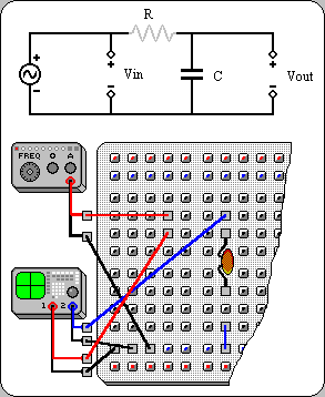
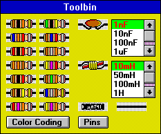
The circuit view contains three basic elements. The schematic circuit shows the circuit to be built in a schematic, or textbook, form. The breadboard is the area where the physical realization of the circuit is displayed. The toolbin contains a selection of components that can be used to build the circuit. Abstract representations of the instruments that are to be connected are shown at the sides of the breadboard. Correct connections on the breadboard are related back to the schematic circuit by displaying the correct connections in black, whereas incorrect or incomplete connections are grayed out.
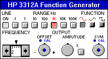
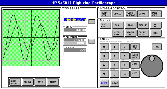
After building the desired circuit, the user moves on to the measurement view to take measurements. To this end, the measurement view is furnished with simulations of an oscilloscope and function generator or power supply and digital multimeter.
 Return to introductory page.